How to Repair an STL File — Check First, Then Fix
Your slicer says the model is non-manifold. Or the preview shows gaps that aren't in the original design. Or the print comes out with missing walls. Before you press a repair button, it helps to know what is actually wrong: almost every broken STL has one of eight defects, most of them are fixable automatically, and one of them is not fixable at all. This guide explains how to identify each defect, compares the repair tools available in 2026, and shows where automatic repair can quietly damage your geometry. Everything here comes from testing a repair pipeline against deliberately broken files. You can download those files below and use them to evaluate any repair tool, including ours.
What Breaks an STL File
An STL file stores triangles and nothing else: three vertices and a normal vector per facet. For a slicer to compute where material goes, those triangles must form a watertight envelope with consistent winding, and every edge must be shared by exactly two faces. There is no checksum and no structure that enforces any of this, so exporters, boolean operations, and 3D scanners routinely produce files that violate it.
| Defect | What you see | Typical cause | Auto-fixable? |
|---|---|---|---|
| Holes | Gaps in the surface; slicer refuses or fills them wrong | Interrupted exports, deleted faces, scan gaps | Yes |
| Flipped normals | Inside-out patches; voids where solid should be | Mirrored geometry, inconsistent booleans | Yes |
| Non-manifold edges | An edge shared by three or more faces | Dangling fins left by boolean operations | Yes |
| Duplicate / degenerate faces | Inflated face count; zero-area triangles | Double exports, extreme scaling | Yes |
| Self-intersections | Parts of the mesh pass through each other | Overlapping solids merged without a union | Usually not needed |
| Debris shells | Floating fragments away from the main body | 3D scans, sloppy merges | Yes |
| Hairline cracks | Seams a fraction of a millimeter wide | Low-tolerance exports | Yes, with a caveat |
| Open surface | A sheet with no thickness at all | A scan patch or a single exported plane | No |
Two of these deserve a note. Self-intersecting solids are usually printable as-is, because modern slicers union overlapping volumes during slicing; in our tests we deliberately leave them alone rather than rebuild the mesh for no benefit. And an open surface is not damage in the usual sense: a flat sheet has no inside, so no repair algorithm can decide what solid it should become. It needs thickness added in a CAD or mesh editing program.
Want to see every defect on this list in the viewer, with its real check report?
STL Defects, IllustratedCheck Before You Repair
A repair tool that only hands back a "fixed" file leaves you guessing about what changed. Usually nothing important did. Occasionally something important did, and this is the case worth designing the whole workflow around.
When I validated our repair pipeline on ten damaged test files, nine repaired cleanly with volumes matching the intended geometry. The tenth was a part with hairline seam cracks, 0.005 to 0.02 mm wide. The repaired file came back watertight and looked normal in a viewer, but welding those cracks had shifted surfaces enough to cut the enclosed volume by 23%. Nothing in the file itself tells you this happened. Only comparing measurements before and after does.
So the workflow this guide recommends is: diagnose first, repair second, verify third. A proper defect report lists triangle and shell counts, open boundary edges, non-manifold edges, winding consistency, duplicates, bounding-box dimensions, and enclosed volume, both before and after the repair. If a dimension on your part matters, check it against the report instead of trusting the repair.
Run a free check on your STL. Check mode analyzes the mesh and gives you the full defect report without touching your file.
Check Your STLRepair Tools Compared
There are more options than most listicles suggest, and the honest answer is that several of them work fine. They differ in what they tell you, how much control you get, and what happens after the repair.
| Tool | Where it runs | Defect report | Notes |
|---|---|---|---|
| ConverterFlow STL Checker & Repair | Browser, free, no signup | Full report with before/after dimensions and volume | STL and OBJ input up to 200 MB; three repair levels; converts onward to STEP |
| Remeshy | Browser, free | None as of July 2026 | Returns a fixed file; the repair itself works, but you get no numbers to verify it against |
| Blender (3D-Print Toolbox) | Desktop, free | Interactive inspection | Full manual control over every vertex; the steepest learning curve here |
| Meshmixer (Inspector) | Desktop, free | Visual defect flags | Capable, but Autodesk no longer actively develops it |
| Slicer built-ins (PrusaSlicer, Cura) | Desktop, free | Warnings only | Patch simple holes at slice time; whether you can export the repaired mesh depends on slicer and platform |
My take: if you live in Blender anyway, its 3D-Print Toolbox gives you the most control and teaches you the most about your mesh. If you want the file fixed in a browser with proof of what changed, that is the gap our tool is built for: the report is the product, and the repair is optional. And if the part is ultimately headed for CAD or a machine shop, repairing and converting to STEP in one workflow saves a round trip through a second tool.
Step by Step: Repairing an STL in the Browser
1. Upload the file to the STL Checker & Repair tool in check mode. The 3D preview highlights open boundary edges in red and non-manifold edges in amber, so you can see where the damage sits before deciding anything.
2. Read the report. It tells you whether the mesh is watertight, how many shells it has, and which defects were found. If the file is already printable, stop here; a repair you do not need is risk you do not need.
3. Pick a repair level. Cleanup only performs the safe operations: welding duplicate vertices, dropping degenerate and duplicate faces, fixing winding and normals, filling holes. Standard adds surface reconstruction for meshes the cheap fixes cannot close. Aggressive additionally snap-welds hairline cracks, the one operation that can move geometry, which is why it is opt-in rather than default.
4. Decide what happens to disconnected shells. The default drops debris below 1% of the surface area, which is right for scan noise. If your file legitimately contains several separate parts, keep them; if you only want the main body, keep the largest shell only.
5. Run the repair and read the after-numbers. The report flags any dimension or volume drift over 1%. If the drift matters for your part, the fix is not a better repair setting; it is re-exporting from the source CAD with tighter tolerances.
Try It on Deliberately Broken Files
These are the actual test files from our validation suite, each engineered to have exactly one category of damage. Download them and run them through any repair tool to see how it behaves and what it reports.
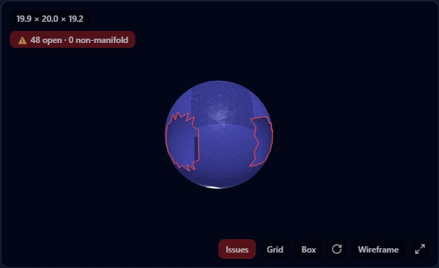
- 01_holes.stlA sphere with two patches of faces removed
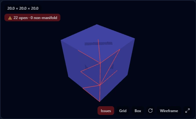
- 03_nonmanifold_fin.stlA box with a dangling triangle on one edge
- 06_shells_debris.stlA solid plus floating noise fragments, like scan output
- 09_seam_gaps.stlHairline cracks; the file that distorts under careless repair
- 08_open_surface.stlA flat sheet; the unfixable case a tool should warn about
What Automatic Repair Can't Do
An open surface cannot become a solid without a design decision about thickness, so our tool warns "this is a surface, not a solid" instead of claiming success. Severely cracked meshes can be made watertight, but as the 23% case above shows, the result may not be the part you designed. And no mesh repair recovers design intent: if the STL came from CAD and the damage is bad, re-exporting from the source file with a sane tolerance beats any repair.
After the Repair
A watertight STL is ready to slice. If the part needs to go further than the printer, into SolidWorks, Fusion 360, or a supplier quote, the repaired mesh can be converted to a STEP solid with selectable faces. Repairing first matters here: mesh-to-BREP conversion fails on broken meshes far more often than slicers do.
Need the part in CAD? Convert the repaired STL to a STEP solid.
STL to STEP ConverterFrequently Asked Questions
Why does my slicer say the STL is non-manifold?
Some edge in the mesh is shared by more than two triangles, or the surface has boundary edges that belong to only one. Slicers need every edge to separate exactly one inside from one outside to compute toolpaths. The usual culprits are boolean operations that left internal faces behind and meshes that were merged without being unioned.
Does repairing an STL change its dimensions?
Usually not measurably. Removing duplicate faces, fixing normals, and capping holes leave the surviving geometry where it was. The exception is welding hairline cracks, which moves vertices by design; in our worst test case that cost 23% of the enclosed volume. Any tool doing that kind of repair should show you before/after measurements, and you should read them.
Can every STL be repaired?
No. A file that is a surface rather than a solid (a scan patch, a single plane) has no inside to close, and a mesh whose damage overlaps the geometry you care about may be repairable only into the wrong shape. In both cases the honest fix is upstream: add thickness in a mesh editor, or re-export from the source CAD.
Do I need to install anything to repair an STL?
Not for most files. Our checker runs in the browser, free and without a signup, up to 200 MB, and accepts OBJ as well as STL. Desktop tools like Blender earn their install when you need manual control, for example rebuilding a specific region by hand.
This guide covers one problem. For the full set of 3D converters, checkers, and calculators, visit the hub.
Browse 3D Tools